Can Radar Level Meters Measure Powders and Bulk Solids? Selection and Installation Guide
Can a non-contact radar level meter monitor cement, flour, plastic pellets, ash, or other bulk solids? Learn how powder level radar works, what dust and vessel geometry affect, and how to plan installation and commissioning.
Can Radar Level Meters Measure Powders and Bulk Solids? Selection and Installation Guide
Cement, fly ash, flour, plastic pellets, feed, mineral powder, and many other materials are stored in silos, bins, and process vessels. A high level can lead to overflow or a disrupted loading operation; a low level can interrupt production. This makes a common project question especially practical: can radar level meters measure powders and bulk solids?
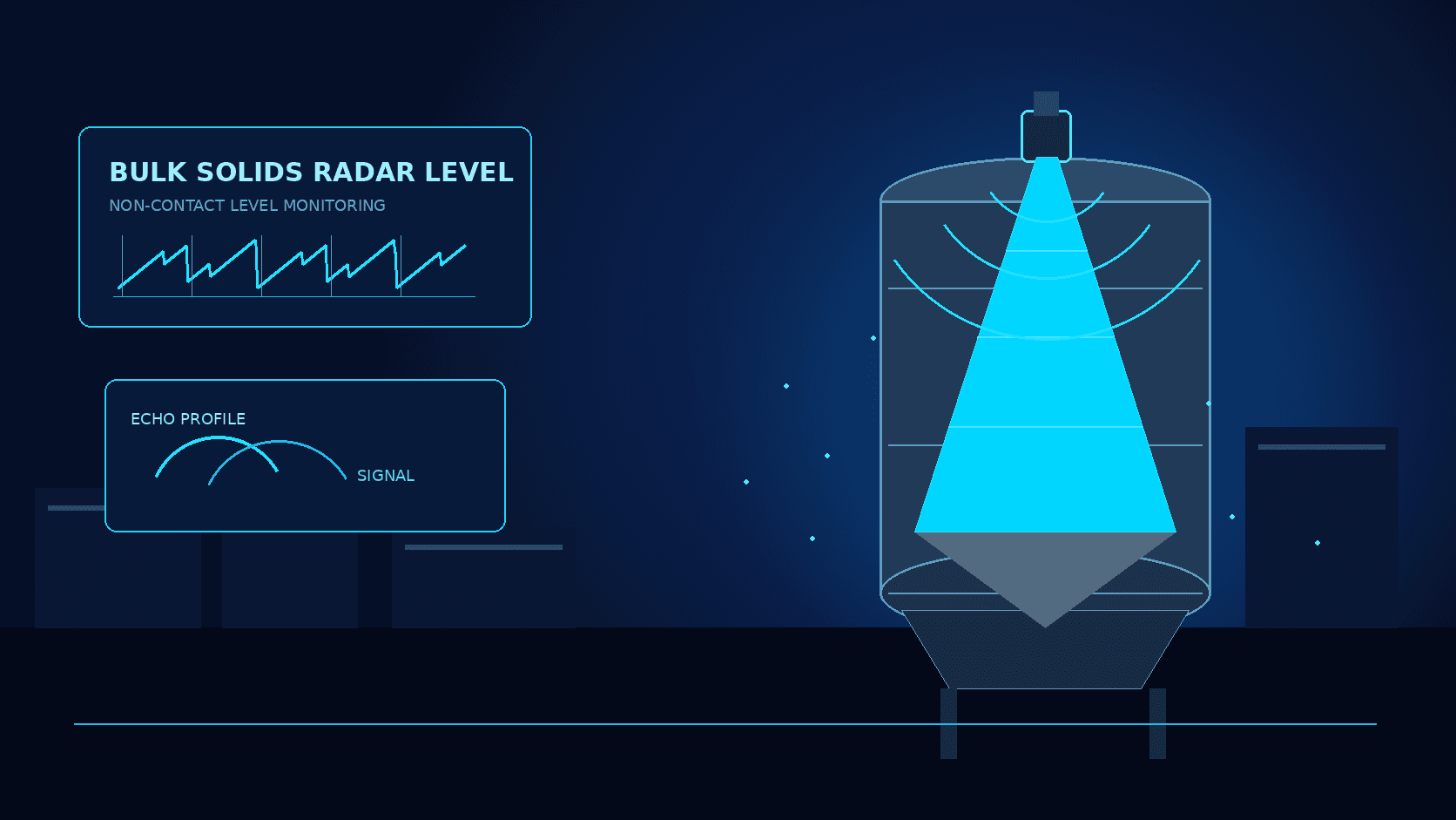
In many applications, yes. A radar level meter for solids is mounted at the top of a vessel, transmits electromagnetic energy toward the material surface, and evaluates the returned signal to determine the distance to that surface. The distance can then be represented as ullage or level. Since the measurement is non-contact, the sensing element does not need to sit in the material stream, which can be valuable in dusty, enclosed, tall, or difficult-to-access installations.
That is not a blanket guarantee for every powder and every silo. A powder surface may be conical, off-center, or continuously changing. Pneumatic filling can create a dense dust cloud. Ladders, braces, fill pipes, filters, and accumulated material near the antenna can create competing reflections. A useful result comes from treating the meter, vessel, material, and process as one measurement system.
How a radar level meter sees a powder surface
A top-mounted radar instrument directs a beam toward the stored material and processes the echo returned from the bulk-solid surface. Its calculation is based on travel time, rather than on a visual view of the material. Depending on the instrument and configuration, the output can be a distance, empty-space value, level, or a signal delivered to a control system.
With powders, the return is influenced by more than vessel height. Dielectric properties, particle size, moisture, bulk density, surface roughness, and angle of repose can all affect the signal environment. Fine dry material entering a vessel can create temporary dust; a low-dielectric material can yield a weaker return; eccentric filling can put the highest point of a material cone away from the vessel center. Proper antenna selection, mounting geometry, and echo handling help distinguish the moving material surface from fixed structure.
The right question is therefore not simply “is this a powder?” It is whether a stable, representative return can be obtained over the operating range and whether the resulting point measurement fits the process decision it is meant to support.
Conditions that should be reviewed before selection
| Site condition | Why it matters | Planning response | | --- | --- | --- | | Material properties and particle form | Echo behavior varies with dielectric properties, particle size, and moisture | Document the material, powder/pellet form, expected moisture changes, and tendency to cake | | Dust and pneumatic filling | A filling event can temporarily disturb the measurement path | Describe filling frequency and severity; assess an antenna and signal-processing approach suited to the duty | | Conical or off-center surface | One measured point may not equal average inventory | Place the beam for the control objective and use an inventory model where appropriate | | Internal structures | Braces, ladders, pipes, and filters can produce fixed echoes | Review section drawings and keep the primary beam away from major obstructions | | Build-up and condensation | Deposits near the antenna can change near-field reflections | Select a suitable process connection and include inspection in the maintenance plan | | Temperature, pressure, and hazardous-area needs | These affect construction, sealing, and compliance configuration | Specify process and area requirements before procurement and confirm the project configuration |
Installation location: start with the vessel, not the mounting flange
A convenient roof nozzle is not automatically the best measurement point. First consider where the material pile forms during filling and discharge, where the radar beam can remain clear, and which area will provide a reading useful to the operator. Avoid pointing directly into the strongest incoming material stream when that stream creates heavy dust or impact. Also avoid a beam path dominated by an inlet pipe, structural member, ladder, or wall.
On many silos, the top is crowded with manways, filling lines, vent filters, safety valves, temperature cables, and level switches. Before installation, obtain a vessel cross-section and mark these items along with the planned beam direction. Confirm the usable process connection, sealing arrangement, and clearance above the highest expected material level according to the selected device documentation and site process requirements.
A conical hopper does not by itself dictate a center mount. The best position depends on the fill pattern, discharge pattern, vessel geometry, and what the reading will control. For example, a level intended to prevent overfill may need a different representative point from a value used for broad inventory trending. Discuss that control purpose before fixing the mechanical location.
Safe access also matters. Non-contact measurement can reduce parts exposed to abrasion, burial, and direct material contact, but it is not maintenance-free. Teams still need a safe way to inspect the enclosure, cable glands, antenna opening, mounting hardware, and surrounding roof area. For tall vessels, this belongs in the site’s isolation, fall-protection, and combustible-dust safety procedures.
Information to collect for a sound selection
A short request that says “measure powder level” leaves out the details that shape performance. A stronger project brief includes:
- Material data: Material name, powder or granule form, bulk density, expected moisture variation, and whether it tends to adhere or agglomerate.
- Vessel data: Height, diameter, hopper shape, operating minimum and maximum level, nozzle locations, and internal structures.
- Process data: Filling method, filling duration, pneumatic conveying, discharge pattern, and mixing or agitation, if any.
- Environmental and compliance data: Temperature, pressure, indoor/outdoor exposure, required enclosure protection, dust-hazard classification, and applicable project standards.
- Control-system data: Whether the site needs local indication, a continuous value, alarm support, or a transmitted signal; plus available power, interfaces, and communications.
This information supports more than instrument selection. It lets the project plan mounting details, cable routing, commissioning, and the relationship between the measured level and a stock estimate. A point level is not automatically a precise inventory total: irregular piles, wall build-up, and off-center filling can make the level-to-volume conversion approximate unless the model is validated.
Commissioning: validate behavior across operating states
Acceptance should not be limited to one stable reading after installation. Where practical and safe, review the indication at empty or low level, during a controlled fill, under normal operating conditions, and near high level. Record the displayed distance or level, process events, fill timing, and any available physical reference. The key checks are continuity, plausible direction of change, and agreement with the material movement known to be occurring.
If a value repeatedly jumps at the same elevation, do not assume dust is the explanation. Inspect beam direction, antenna cleanliness, fixed structural echoes, near-field configuration, empty-vessel mapping, and parameter settings. Short disturbances during filling may need to be interpreted with signal-quality information, time continuity, and process state—while still preserving the real changes that matter for safe control.
For applications where level feeds a material-balance or inventory calculation, set a review method from the beginning. Compare estimated volume or mass against weigh-scale data, loading records, or periodic inventory checks. The goal is not to force a single sensor to claim more certainty than the vessel geometry allows; it is to understand and manage the remaining uncertainty.
Radar versus contact methods for bulk solids
Point switches, rotary paddles, weighted systems, guided-wave devices, and other methods all have appropriate roles. The non-contact radar approach keeps the sensing path above the material surface and can provide a continuous level trend, which may reduce direct exposure to abrasion, loading forces, and buried components. This is often useful for high silos, sealed vessels, and dusty process areas.
Selection should follow the control architecture, however. A high-high level safety interlock may still require a separate point switch as an independent protection layer. A continuous radar measurement may serve inventory trend monitoring, while a scale or material-accounting system remains the reference for finer reconciliation. The most resilient arrangement matches the measurement method, alarm layers, verification process, and maintainability to the site’s risks.
Frequently asked questions
Can radar level meters measure very light powders?
They can be considered, but the material and vessel conditions must be confirmed. A light, low-dielectric, or loose material can produce a weaker or more distributed return, and filling dust can add transient interference. Use actual material details and installation information for selection and, where necessary, field validation rather than deciding from the material name alone.
Does dust make radar level measurement unusable?
Not necessarily. Dust is a design consideration, not an automatic rejection of radar. Its effect depends on concentration and duration, antenna cleanliness, beam path, filling arrangement, and usable echo quality. Continuous high-dust duties should be fully described during project engineering so the configuration and commissioning plan address the actual condition.
Can one radar reading directly provide silo inventory?
It can support an inventory estimate, but the conversion needs care. Level-to-volume calculations depend on vessel geometry and material surface shape; off-center piles, conical heaps, and wall build-up create uncertainty. For commercial reconciliation or tightly controlled inventory, compare the estimate with weighing, loading records, or periodic stock checks.
Conclusion
Radar level meters can support continuous monitoring of many powders and bulk solids. The dependable path is to understand the material, vessel, and process first; select a representative beam location; and validate the indication across real operating conditions. When dust, surface shape, internal structure, and safe maintenance access are designed into the project from the start, non-contact radar level data can provide practical support for replenishment, alarms, and production management.