Can Structural Monitoring Radar Measure Bridge Deflection? Deployment and Interpretation Guide
Can structural monitoring radar measure bridge deflection? Learn what radar observes, how line-of-sight geometry and reference design affect results, and how to deploy a practical bridge displacement monitoring system.
Can Structural Monitoring Radar Measure Bridge Deflection? Deployment and Interpretation Guide
Can structural monitoring radar measure bridge deflection? In a suitable geometry, radar can track relative movement or movement change of a visible bridge area along the radar’s line of sight. That makes it useful for observing displacement trends and event responses associated with traffic loading, temperature, construction activity, or an unusual incident. It does not mean that any radar position will directly return a complete, engineering-grade vertical deflection value for every bridge.
Bridge deflection is spatial structural movement under load. A sound monitoring project defines the measurement question, coordinate direction, reference arrangement, quality controls, and interpretation process before selecting the sensor. Radar is one source in that measurement chain. Structural assessment, design verification, safety decisions, and intervention should remain with the responsible engineering team and follow the applicable project requirements.
What Does a Structural Monitoring Radar Actually Observe?
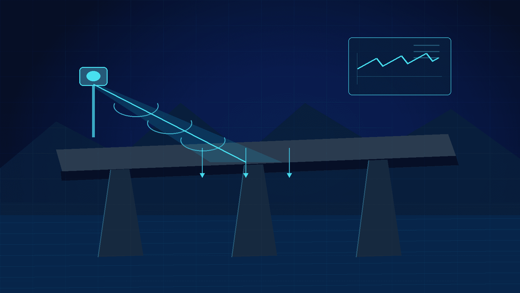
A structural radar system generally follows movement through changes in the returned electromagnetic signal from a target area. Its direct measurement sensitivity is predominantly in the direction from the radar to that target: the line of sight. When the line of sight does not align with the desired vertical bridge deflection direction, the measured displacement is a component of the true movement rather than the full movement itself.
For example, a radar looking obliquely at the underside of a span may observe a combination of vertical response, lateral movement, and local rotation projected into one line-of-sight signal. If vertical deflection is the engineering quantity of interest, the project should account for geometry through the selected observation angle, structural geometry, control targets, multiple viewpoints, or comparison with other instruments. Whether a single measured area represents a critical section is also a structural question, not a default property of the radar.
| Monitoring question | Information radar may provide | Conditions to confirm | | --- | --- | --- | | Does a visible area move during a loading event? | A line-of-sight displacement time history | Stable target response and time alignment with the event | | Is response at a key span changing relative to baseline? | Trend or event response for the observed area | Observation geometry, stable reference, and repeatable processing | | Is movement occurring near a bearing or expansion joint? | Relative motion of a specific visible region | Visibility, target definition, and local structural effects | | Is long-term deformation evolving? | Change trend under consistent installation conditions | Temperature, seasons, support stability, and data-quality controls |
Where Is Non-Contact Radar Useful for Bridge Deflection Monitoring?
Non-contact radar can be valuable where placing sensors directly on the bridge is difficult, disruptive, or unsafe. Depending on access and geometry, it can observe a visible part of a bridge from a stand-off location and reduce the need for work at height, over water, or inside traffic space. Potential applications include controlled load tests, focused observation during construction, comparison before and after maintenance, and follow-up observation after an incident.
Suitability remains site-specific. The underside of a span, a pier-related region, a bearing area, or another target must be within a usable field of view. Passing vehicles, pedestrians, temporary equipment, vegetation, guardrails, or other structures must not create persistent occlusion. Weather, wind, surface wetness, long observation paths, and changing site activity can affect signal quality or interpretation. A single viewing direction may also be insufficient when a project needs several spans, several components, or three-dimensional movement.
Target Selection and Reference Design Matter
Bridge surfaces are not automatically ideal measurement targets. Steelwork, concrete, coatings, curved surfaces, wet areas, and attached components can produce different responses. A site survey or controlled trial is useful for confirming that the intended target remains identifiable under realistic conditions. Where a dedicated reflector is proposed, its placement should be approved within the structural and operational design; it should never be added casually in a way that changes the bridge or creates a hazard.
A stable reference is equally important. If the radar support moves because of vibration, settlement, thermal expansion, or an unstable mounting surface, that motion can be mistaken for structural displacement. Projects can reduce this risk by using a robust independent mounting location, documenting support condition, observing a reference area where appropriate, and comparing results with independent measurements. When several systems are used, their time stamps, coordinate definitions, sampling strategy, and event records should be reconciled before results are combined.
Practical Deployment Steps for Bridge Displacement Radar
1. Define the monitoring decision
Document whether the work supports construction control, a load test, periodic condition review, or an alerting process. This determines target locations, sampling needs, observation duration, retention requirements, and escalation procedures. A displacement alert threshold should not be based on one isolated trace. It requires an approved basis that considers design limits, baseline behaviour, temperature effects, operating conditions, and project rules.
2. Review line-of-sight geometry and obstruction risk
Review drawings and the actual site together. Record the radar-to-target distance, viewing angle, expected movement direction, visible component, permanent reflectors, and likely traffic or construction obstructions. Where the expected movement is nearly perpendicular to the line of sight, assess whether the projection error is acceptable. If not, reposition the radar, add a viewing point, or use a complementary measurement method.
3. Design for the outdoor bridge environment
Bridge sites can expose equipment to sunlight, temperature cycling, rain, vibration, wind, salt, lightning risk, and changing construction conditions. The enclosure, power source, communications, cable restraint, grounding, and surge measures should follow the approved design and the device documentation. Supports should be sufficiently stiff and should not be fixed to a guardrail, movable component, or temporary item that may vibrate or shift. Record the installed arrangement with photographs and include it in inspection routines.
4. Create a data-quality workflow
A continuous chart is not automatically a continuous valid measurement. Automated or manual review should identify communication loss, target occlusion, changes in return quality, rain, construction activity, maintenance, and other relevant events. Before treating an apparent displacement as structural behaviour, check the reference, support condition, return quality, timing, and site context. Compare significant events with inspection findings or an independent measurement where feasible.
How Radar Works With Other Bridge Monitoring Methods
Radar is often most useful as a complement rather than a one-for-one replacement. Contact displacement sensors can provide local relative displacement at a clearly defined installation point. Accelerometers are sensitive to dynamic response. Total stations or levelling can provide periodic spatial control. Visual inspection and imaging contribute visible condition evidence. The method mix should be selected for the engineering question, not merely for a sensor label.
| Method | Typical strength | Main limitation | Complementary role with radar | | --- | --- | --- | --- | | Non-contact structural monitoring radar | Stand-off observation of visible targets and event trends | Primarily line-of-sight; geometry and occlusion matter | Continuous trend or event observation at key visible areas | | Contact displacement sensor | Defined local relative displacement | Requires installation, reference, and wiring | Checks critical sections or bearing-related locations | | Accelerometer | Dynamic and vibration response | Converting to displacement requires careful processing | Helps associate movement with vibration, wind, or traffic events | | Total station or levelling | Traceable periodic control | Usually not high-frequency continuous observation | Verifies reference and long-term change periodically |
Frequently Asked Questions
Is a radar displacement reading the same as vertical bridge deflection?
Not necessarily. Radar first observes motion along its line of sight. It can support interpretation of vertical deflection only when target location, observation geometry, coordinate conversion, and verification have been explicitly designed for that purpose.
Can one radar determine whether a bridge is safe?
No. Bridge safety assessment requires design information, inspection, operational and environmental context, other monitoring evidence where relevant, and professional engineering judgment. Radar can supply useful trend and event evidence, but it is not a substitute for a complete structural assessment process.
Do passing vehicles affect bridge radar monitoring?
They can be both the load event being observed and a source of target occlusion or additional reflections. The monitoring plan should identify these conditions and use target selection, quality flags, and event records to reduce ambiguity.
What should be included in acceptance of a radar bridge-monitoring installation?
A practical acceptance record covers target and support locations, line-of-sight and obstruction checks, power and communications, time synchronisation, reference arrangement, trial data quality, comparison with an independent method where required, abnormal-event handling, and handover documentation. The final acceptance scope should follow the contract, design documents, and applicable standards.
Conclusion
Structural monitoring radar can be a useful tool for observing bridge displacement and deflection-related trends when its line-of-sight measurement is placed within a clear engineering framework. Define the question first, then design target selection, geometry, support stability, reference strategy, and data validation. That approach turns non-contact observations into evidence that is more explainable, traceable, and useful for bridge operation and maintenance.